http://www.dixdesign.com/lofting1.htm
CONTOUR LINES FOR SURFACE DRAWINGS
In the the combined aerial image and topographic drawing below we can see that the contour lines are defined by projections of horizontal planes ( like slices) at different heights or altitude levels. By constraining the projections to any one of the three orthogonal planes ( X,Y, or X, Z or Z,Y ) and maintaining a consistent dimension between each line the resulting patterns define the surfaces of irregular and complex forms.
For geographers the planes are defined as parallel to the concept of level defined by a body of water and the concept of sea- level as the origin or zero (0). As it turns out the concept of level defined by water also defines the concept of level and horizontal lines in the nautical designer's drawing.

While contour maps of geographical features only look at them from above, on a drawing of a boat hull lines drawing we are looking at the hull from three directions and each view has it's own story to tell about the character of the hull.
By creating projections in more than one dimension and making the distance between the projected planes
smaller a greater definition or surface resolution can be achieved.
Boat hulls are characterized by symmetrical forms with shapes that intend to optimize their efficient movement through fluid. As such they are typically longer in proportion along the axis of their forward direction of movement than in the other two dimensions. They are also characteristically symmetrical about that same axis in the vertical plane to result in fluid dynamics that allow for the boat hull to move in a straight line.
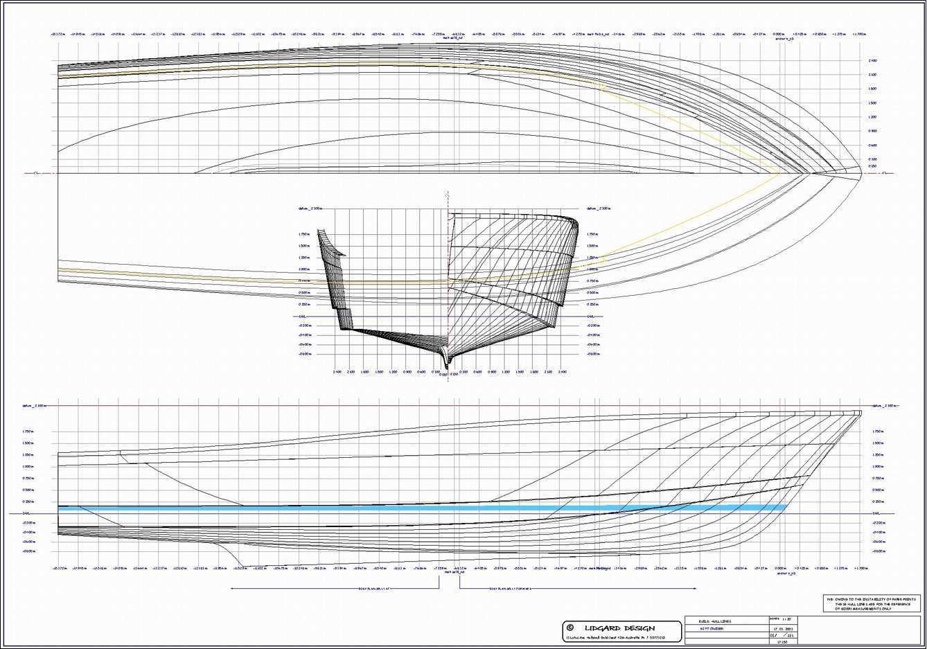
The drawing below shows three orthographic views in the respective X, Y, and Z planes
( side view, plan or top view and end view ) of a sailing boat hull. These are essentially the same drawing conventions used by architects to describe a building however, because the rounded boat hull surfaces are defined by complex compound curves and have few features such as flat surfaces or corners to use as measurement reference points, a different method is used to define the hull shape.
To define the hull shape of a boat - Orthogonal lines are essentially projected in the three respective axis the same way that the contours on a geographic chart define the shape of land forms on a topographic map.

Side View and Buttocks
The side elevation shows the boat as if it were being viewed on the dock, with the
sheer line being the extreme upper edge of the hull and the
profile line forming the lower perimeter of the hull from stemhead to transom, usually along the centreline for a monohull.
Between the sheer and profile lines are a number of curved lines called buttocks (Butt 1 to Butt 3 on the drawing), those closest to the profile line being pretty much parallel to it and those further away being progressively less parallel. The buttocks are the side view contours of the hull and each connects up all points on the hull surface which are the required distance from the hull centreline. If the buttock under consideration is a 500mm buttock (Butt 1 in this case), all points along that line are 500mm from the hull centreline. If the hull was cut through longitudinally 500mm from centreline, the 500mm buttock shape would be the shape of the cut.
Most hulls will have buttocks which are gently curved in the bow areas with some flatness in the lower areas aft and fairly tight curvature in the topsides aft. A slab sided hull will have fairly vertical aft endings to the buttocks while the top ends aft will turn forward on a hull with tumblehome. A clipper bowed hull will have buttocks which curve forward high in the topsides near the bow and a hull with a firm turn to the bilge will show it with a fairly tight curve in the buttocks near the waterline in the bow areas.
The buttocks are the best indicators of the off-wind performance potential of a hull. At the stern they show at what angle the water will be flowing as it comes out from under the hull. A steep buttock indicates a large quarter wave and a flat angle shows a flat and clean wake. An upward curve to the buttocks closest to centreline as they approach the stern will cause the hull to squat as the stern is sucked down by the water following the curve.
Plan View and Waterlines
The plan view shows the boat as if it were upside down with the viewer looking down at it. At the extreme outer edge is the sheer line while all the lines inside of the sheer line are known as waterlines (WL -1 to WL 3 on the drawing) and are the plan view contours of the hull.
The line at which the designer intends the boat to float is called the design waterline and is normally designated DWL on the drawing. The shape which it is drawn shows the shape of the water plane on which the boat rests when it is stationary and is equivalent to a horizontal cut through the hull at that level. The other waterlines are all related to the DWL by their heights above or below DWL and each shows the shape of a horizontal cut at it's own level.
A fine bowed boat will have waterlines at and close to DWL which are straight lines in the bow area and meet the centreline at a relatively small angle. Conversely, a full bowed boat will have considerable curvature to the forward waterlines and they will meet the centreline at a large angle. Below DWL, a hull with U-shaped bow sections will have waterlines which turn in suddenly and meet the centreline at 90 degrees while V-shaped sections will give waterlines which have little turn in and meet the centreline at an angle. A boat with a flat stern will have a lot of curvature to the waterlines aft, meeting the centreline at close to 90 degrees while those of a hull with Vee aft will have less curvature and meet the centreline at an angle. Looking at the topsides, a slab sided boat will have the waterlines above DWL converging on each other for much of the hull length around the maximum beam and a boat with tumblehome will have one or more waterlines projecting beyond the sheer line for the length of the tumblehome.
The waterlines are the best indicators of the up-wind potential of the hull, telling the eye whether the bow will cut cleanly through headseas with little effort or require a lot of brute force to push the seas aside. The relationship between the bow and stern waterlines indicates the extent to which the boat will change trim as she heels over. A very fine bow combined with a very full stern will cause the bow to be depressed considerably as the heel angle increases.
Body Plan and Stations
The end view of the hull is known as the body plan or the cross-sections and is sometimes drawn superimposed over the side view. Only half of each section is drawn with those from the bow to the point of maximum beam drawn on one side of centreline and the rest on the other side. This gives a view looking aft and one looking forward. Each section shows the shape of the hull at a specific position along it's length.
The body plan gives the clearest picture of the overall shape of the hull with regard to stability characteristics and seakindliness. It shows whether the hull has firm or slack bilges, Vee or U-shaped bow sections, Vee or flat stern sections, amount of flare, flam, tumblehome and a host of other subtle characteristics.
None of the three views tells the complete story of the hull by itself. They all need to be read and interpreted together.
On the lines drawing is a grid which forms a background to the lines of the hull and, on inspection, it will be seen that the grid for each view is different from that of both other views. Looking at the side view of the hull, the grid is composed of horizontal lines which are the waterlines on the plan view and vertical lines which are the sections of the body plan. The plan view has longitudinal lines which are the buttocks of the side view and transverse lines which are again the sections of the body plan. Similarly, the body plan has vertical lines which are the buttocks of the side view and horizontal lines which are the waterlines of the plan view. Each curved line in each view is, thus, a straight line and part of the grid in both of the other two views.
To confuse the reader, the section lines on the side and plan views are not called sections but are stations. The sections which are seen on the body plan are sections on the relevant stations.
The usual method of referencing the stations is for station 0 to be at the point where the profile line in the side view crosses DWL at the bow and station 10 at the point where it crosses at the stern. The stations between are equally spaced, giving a station spacing of 10% of waterline length. Other methods of spacing and/or referencing stations are sometimes seen, such as numbering from stern to bow. Often additional stations will be used to help define the bow and stern, such as stations 1/2 and 9 1/2. Large boats will sometimes have more than ten stations between the extremes of DWL and small boats may have less.
The section of hull ahead of station 0 may include a negative station or two but is more likely to have some dimensions on the drawing to define the curve. The tip of the bow will probably be referenced FP which stands for Forward Position and the stern would be AP for Aft Position. There will be dimensions on the drawing to position both FP and AP, both of which form part of the grid.
Waterlines are numbered or are referenced by their distances above or below DWL or, sometimes, their distances above a base line. Buttocks are numbered or are referenced by their distances from hull centreline.
Diagonals
On the body plan there will normally be one or more diagonal lines (Diag A to Diag C on the drawing) which are usually referenced alphabetically. These are used by the designer to define the hull mainly in the area of the turn of the bilge. The diagonals do not form part of either of the side or plan views but are drawn as curved lines on the opposite side of the hull centreline from the plan view.
Chine Hulls
The principles of a lines drawing for a single chine, multi-chine or radiused chine hull are similar to those described above for round bilge yachts. The difference is that such hulls have convenient corners in their surfaces which can be used as reference points for setting them out, eliminating the need for contour lines. As a result, waterlines, buttocks and diagonals are not required and the drawing, offset table and lofting are considerably simplified. The DWL will still appear on the drawing but, in the lofting process, will only be used as a datum. The sheer and chine lines will appear in all three views and the profile line will only be on the side view, coinciding with the centreline on the other two views. On the body plan, the chines of each section will generally be linked by straight lines.
Fig 2 shows a line drawing for a multi-chine hull with fin keel, transom hung rudder and planing boards. In this case, it has a flat central panel spanning from chine 1 on one side to chine 1 on the other side. As a result, chine 1 and the profile are the same line from station 0 to AP. A hull with Vee on the centreline will show a seperate profile line.

A single chine design which has a large amount of twist to the panels (change of angle from station to station) will probably have conically developed surfaces. This will allow the sheet material from which the hull skin is formed to take it's natural curve without undue stress. The lines drawing for such a hull will have waterlines and/or buttocks in the areas of conical development so elements from both types of lines drawing will be present. A multi-chine hull will not normally need conical development because the hull form demands less twist and the narrower panels can accept more twist without problems appearing.
Table of Offsets
The table of offsets which accompanies the lines drawing is a tabular representation of the body plan, ie a list of measurements. There are various methods used in drawing up the table and it should be very clear by the wording on the table which method is used. The method which I always use is very simple and references everything vertically to the DWL and horizontally to the hull centreline, all measurements being to the outside of the hull skin. A minus sign in front of a vertical offset indicates a downward measurement from DWL while all others are measured upward.
Fig 3 shows a table of frame offsets for a motor yacht hull with two chines, the lower one being radiused so it has been called a ghost chine. The table for a round bilge design will have a similar layout with more rows. In the section for measurements above/below DWL the offsets for buttocks would replace those for chines and in the section for measurements from centreline the offsets for waterlines and diagonals would replace those for chines. The offsets for diagonals are always measured from centreline along the diagonals to the hull skin.
for more about specific Nautical Terms
http://www.marineinstitute.org/nautical%20terms.htm
No comments:
Post a Comment